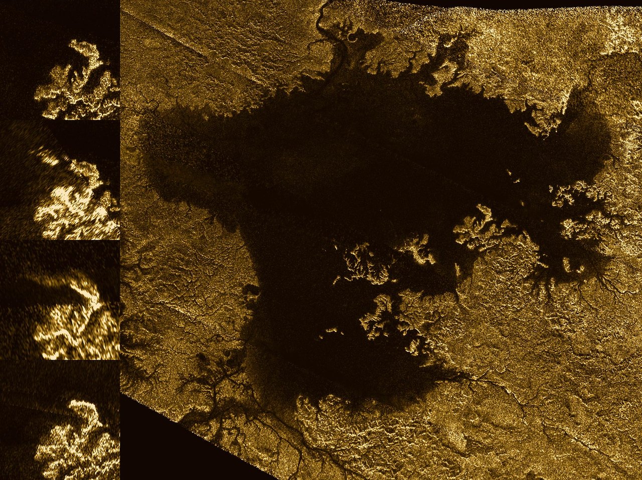
PIA20021 was taken from the RADAR instrument and shows the evolution of a transient feature in the large hydrocarbon sea named Ligeia Mare on Saturn's moon Titan.
See
Volume 1-Mission Overview, Science Objectives and Results for full science report. The technical report is in other volumes archived at the Jet Propulsion Lab.
Mission Science Highlights and Science Objectives Assessment provides a brief overview of the mission
About RADAR
RADAR was a multimode Ku-band (13.78 GHz, 2.17 cm) instrument onboard Cassini. RADAR's primary goal was to pierce Titan's thick veil of smog and aerosols
to map its surface. While NASA's Jet Propulsion Laboratory was responsible for the overall design of the instrument
and the spacecraft interfaces with RADAR, Agenzia Spatiale Italiana was tasked with constructing the Radio Frequency Electronics Subsystem and the
high-gain antenna, which was used both for downlink and RADAR observations.
Among the principal science goals of the instrument were:
- determining the physical state, composition and topography of the surface of Titan
- establishing the existence of surface liquid on Titan
- measuring global circulation and global temperatures on Titan
- sounding Saturn's atmosphere to gain insight into its dynamics using NH3 as a tracer
- constraining the non-icy component of the particles comprising Saturn's rings
- constraining the compositional and thermal properties of Saturn's icy satellites
A more comprehensive list of the science objectives pursued by RADAR is provided in the
Cassini Mission Final Report (In preparation).
Radio Detection and Ranging (RADAR) operated in four modes: Synthetic Aperture (SAR) imaging, altimetry, scatterometry and radiometry.
In each of the first three modes, RADAR was used as active source, pinging the target and recording the
subsequent echo. When used as a radiometer, RADAR passively recorded its target's natural microwave radiation.
RADAR was capable of creating images at resolutions as fine as 0.35 km in SAR mode, and as fine as 7 km in the radiometry
and scatterometry modes. Radiometry data were used to measure ring temperature. Additionally, RADAR altimetry obtained 90-150 meter vertical resolution.
Additional references that may help understand the data include:
Note that the following table represents design parameters. Actual values vary - see the referenced papers for details
RADAR Instrument Characteristics*
| Observation Mode |
SAR |
Altimeter |
Scatterometer |
Radiometer |
| Frequency (GHz) |
13.78 |
13.78 |
13.78 |
13.78 |
| Peak Power (W) |
46.2 |
46.2 |
46.2 |
n/a |
| Look Angles |
| Cross-Track(º) |
5-20 |
0 |
±6 to ±12 |
±6 to ±12 |
| Along-Track(º) |
0 |
0 |
±6 to ±12 |
±6 to ±12 |
| PRF (kHz) |
1.8-6.0 |
4.7-5.6 |
1.0-3.0 |
n/a |
| Pulse Width (µs) |
200-400 |
150 |
500 |
n/a |
| Bandwidth (MHz) |
0.43, 0.85 |
4.25 |
0.11 |
135 |
RADAR Instrument Characteristics at Titan*
| Observation Mode |
SAR |
|
Altimeter |
Scatterometer |
Radiometer |
|
High Resolution |
Low Resolution |
|
|
| Altitude (km) |
1000–1600 |
1600–4000 |
4000–9000 |
9000–22500 |
1000–100000 |
| Incidence Angle (º) |
21–30 |
15–28 |
0 |
0–30 |
0–80 |
| Resolution |
| Azimuth (km) |
0.35–0.41 |
0.41–0.72 |
24–27 |
55–140 |
6–600 |
| Range (km) |
0.48–0.64 |
0.48–2.70 |
24–27 |
55–140 |
6–600 |
| Vertical (m) |
n/a |
n/a |
60 |
n/a |
n/a |
| NEσ0 at boresighta (dB) |
-28– -21 |
-25– -15 |
-3– -35 |
-4– -36 |
n/a |
aNEσ0 is noise-equivalent backscattering coefficient, a measure of the signal detection sensitivity
* includes values taken from Tables I and II in Elachi et al. (2004) in Space Science Reviews
RADAR Data
Data Search Tools
- The RADAR User's Guide provides an introduction to the capabilities of the radar instrument and products available to the user.
- The Event Calendar is an interactive event-finding tool that can be used to search for data associated with particular events.
- The PDS Imaging Atlas helps search for data files by various parameters including target, geometry, and date.
- The Master Schedule is a time-ordered listing of observations by all instruments. This may help find data based on particular events, however the Image Atlas tool linked above will be much simpler to use in most circumstances.
- Titan Trek helps search for RADAR data using an interactive map of Titan.
- The table of RADAR Observations (XLSX) lists the dates and targets of all RADAR observations.
Browse Raw Data Products
RADAR Data Volumes are located at the PDS Imaging node. There is a separate volume for each observation.
Short Burst Data Records (SBDRs)
- SBDRs include instrument telemetry and calibrated science data in burst order. It excludes raw echo data and altimeter profiles. For every RADAR pass, an SBDR record is produced for every burst.
Long Burst Data Records (LBDRs)
- LBDRs are the same as the SBDR but include a raw echo data array as well. The array comprises 32,768 32-bit IEEE floating-point values, and contains the active-mode time-sampled data obtained during the receive window. The length of the array corresponds to the maximum amount of echo data that can ever be obtained from a single burst.
See the User's Guide, the SISs (listed in the 'Analyzing RADAR Data' section below) or the Imaging Node Cassini-Huygens Page for more information.
Basic Image Data Records (BIDRs)
- BIDRs data files are single-pass, calibrated and gridded SAR image data, formatted as gridded (raster) maps of Titan. The BIDRs are produced in an oblique cylindrical coordinate system. The extent of each BIDR product is the minimum bounding rectangle of the area of coverage in this projection for nominal SAR.
Altimeter Burst Data Records (ABDRs), ABDR Summary Files (ASUMs)
- ABDRs include the altimeter profile (an intermediate processing result between sampled echo data and a final surface height estimate),but not the echo data. Note that LBDRs include the echo data but not the altimeter profile, and SBDRs include neither. The ABDR and ASUMs only cover time periods when the instrument is in altimetry mode; ASUMs have altimetry results in a CSV format).
STDRs (SARTopo data records)
- STDRs contain profiles of Titan surface heights above the reference sphere and above the geoid. Each record contains a single long (1000s of km), narrow( ~10-km) profile between two SAR beams (antenna feeds) within a single SAR image (BIDR). The files are comma separated values files. Each line in the file contains height estimates and ancillary data that correspond to a specified small region in the BIDR image. A separate SARTopo file is produced for each SAR beam overlap profile. The SARTopo implementation yields 1-5 parallel profiles in each SAR pass. There are 5 antenna beams and thus 4 overlapping regions between them. An additional fifth profile is produced by combining the overlaps between beams 2 and 3 and beams 3 and 4.
Additional information can be found at the
Imaging Node Cassini-Huygens Page.
Derived Data Products
- Titan Trek allows users to download mosaics of Titan and the shape model/DEM
- The RADAR User's Guide can be helpful to learn more about higher order products
- Geologic Maps (a.k.a Geomorphologic Maps) of Titan are derived from SAR and HiSAR swath mosaics, and where these are not available, from global radiometry and ISS global mosaics. The maps show the major geomorphologic classes of Titan (Craters, Mountains, Labyrinths, Plains, Dunes, and Lakes) as described in Malaska et al., (2016) (DOI: 10.1016/j.icarus.2016.02.021). These maps are available as registered GeoTIFFs ready for installation in GIS programs.
- Titan Global Shape Model contains a variety of different models for the global shape of Titan obtained by interpolation or by least-squares fitting to RADAR altimetry and SARTopo data.
- Radiometer Maps include data from pole-to-pole scans and are tabulated in time ordered tables of point-by-point of brightness temperature and other parameters. Residual maps interpolated on a regular grid in cylindrical coordinate are also included.
- RADAR Beam 3 Only SAR (coming soon) includes SAR images produced using only the central beam (beam 3) of the instrument's five beams. Beams 2 and 4 overlap part of the beam 3 footprint and sometimes those beams are used in the SAR but the beam 3 measurement has less noise.
- RADAR - SAR Images from each flyby are derived from Cassini RADAR Basic Image Data Records at 256 pixels/degree. These versions have had systematic biases due to thermal and quantization noise, and systematic variation due to incidence angle have been removed. For more information on this process, see the User's Guide.
- RADAR Digital Map Products include eight different types as listed below. All eight types are gridded (raster) maps of Titan in Equirectangular projection. Many of these data sets consist of maps of both a "primary" variable such as backscatter, possibly normalized in more than one way, and supplementary quantities such as resolution and emission angle. In addition, separate maps may be provided for individual observation sequences and for multiple map quadrangles. Work is in progress on making the archive of these products PDS4-compliant. In the meantime, the data files and indices (in PDS3 format) are publicly available at https://data.astro.cornell.edu/RADAR/
- Pass Radiometry Data Record (PRDR) (coming soon) -
Brightness temperature as measured in a single sequence of a single flyby, along with maps of geometric parameters. Similar to PSDR but radiometry data.
- Pass Scatterometry Data Record (PSDR) (coming soon) -
Real aperture backscatter cross section as measured in a single sequence, along with maps of geometric parameters. Similar to PRDR but scatterometry data.
- Global Radiometry Data Record (GRDR) (coming soon) -
Mosaic of all PRDR normalized brightness temperatures, with highest resolution measurements on top, plus geometric parameters and an index map identifying the PRDR from which each pixel was derived.
- Global Scatterometry Data Record (GSDR) (coming soon) -
Mosaic of all PSDR normalized backscatter cross-sections, with highest resolution measurements on top, plus geometric parameters and an index map identifying the PSDR from which each pixel was derived.
- Global Topography Data Record (GTDR) (coming soon) -
The GTDR is a mosaic of absolute elevation values obtained by altimetry and SARTopo throughout the mission. (Individual PTDRs are not provided because the overlaps between them are very small.) Also interpolated elevation data and spherical harmonic and ellipsoid model fits.
- Mosaicked Image Data Record (MIDR) (coming soon) -
Mosaics of individual SAR images (BIDRs). Separate mosaics are provided for the highest resolution main swaths and the lower resolution observations, as well as the combination of both.
- Repeat Image Data Record (RIDR) (coming soon) -
Individual SAR images resampled to the global Equirectangular projection, along with geometric information (emission, polarization, and look azimuth angles) needed for backscatter and stereo analyses.
- Digital Topographic Model (DTM) (coming soon) -
Models of elevation (relative to 2575 km reference) obtained by stereo radargrammetry or radarclinometry (shape from shading). Radargrammetric DTMs are accompanied by orthorectified versions of the source images, with topographic parallax removed.
Analyzing RADAR Data
Once data products have been selected and retrieved, users will need appropriate software to read, manipulate and display that data.
Software packages that will enable users to make use of RADAR data (some for cost and some free) and their sources (as of summer 2018) are listed below.
| Application | Notes |
|---|
ArcGIS
www.arcgis.com | Reads ISIS CUB files (which are very similar to PDS images), but does not support all projections. Specifically, RADAR's oblique cylindrical projections
are not supported without running the plug-in PDS2ISIS (Images may be loaded, but they must be reprojected to use the cartographic capabilities.) |
FIJI/ImageJ
fiji.sc | ImageJ is now called FIJI ("Fiji Is Just ImageJ"). It reads PDS, ISIS 2, and ISIS 3 (only BSQ—not tiled—formats) with plugins. |
ISIS 3
isis.astrogeology.usgs.gov | ISIS 3 is the standard tool to analyze RADAR data files, and has
step-by-step tutorials on how to process RADAR data. |
Matlab
www.mathworks.com | Can read the images using any number of readers that have been submitted to the public File Exchange. |
Photoshop
www.adobe.com/Photoshop | Photoshop will read the 8-bit BIBQ after inputting the correct dimensions and label length. |
QGIS
www.qgis.org | Reads ISIS CUB files (which are very similar to PDS images), but only does not support all projections. Specifically, RADAR's oblique cylindrical projections
are not supported without running the plug-in PDS2ISIS (You can load the images, but you must reproject them to use the cartographic capabilities.) |
Build your own software
| If users wish to write their own software, or need to know details about file formats or contents, they should read the appropriate Software Interface Specification (SIS):
|
Reference herein to any specific commercial product, process, or service by trade name, trademark, manufacturer, or otherwise, does not constitute or imply its endorsement by the United States Government or the Jet Propulsion Laboratory, California Institute of Technology